


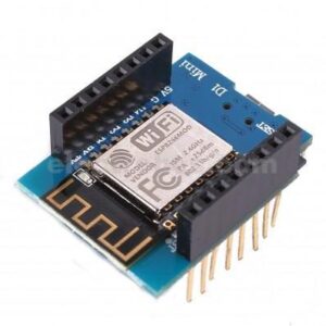
The ESP8266 ESP-01 is a Wi-Fi module that allows microcontrollers access to a Wi-Fi network. This module is a self-contained SOC (System On a Chip) that doesn’t necessarily need a microcontroller to manipulate inputs and outputs as you would normally do with an Arduino, for example, because the ESP-01 acts as a small computer. Depending on the version of the ESP8266, it is possible to have up to 9 GPIOs (General Purpose Input Output). Thus, we can give a microcontroller internet access like the Wi-Fi shield does to the Arduino, or we can simply program the ESP8266 to not only have access to a Wi-Fi network, but to act as a microcontroller as well. This makes the ESP8266 very versatile, and it can save you some money and space in your projects.
Features :
Wi-Fi Direct (P2P), soft-AP
Integrated TCP/IP protocol stack
It features an integrated TR switch, balun, LNA, power amplifier and matching network
Equips integrated PLL, regulators, DCXO and power management units
Integrated low power 32-bit CPU could be used as an application processor
SDIO 1.1 / 2.0, SPI, UART
STBC, 1×1 MIMO, 2×1 MIMO
A-MPDU & A-MSDU aggregation & 0.4ms guard interval
Wake up and transmit packets in < 2ms
Standby power consumption of < 1.0mW (DTIM3)
Package Includes :
1 x ESP-01 ESP8266 Serial WIFI Wireless Transceiver Module
Note:
The ESP8266 Module is not capable of 5-3V logic shifting and will require an external Logic Level Converter. Please do not power it directly from your 5V dev board.
This new version of the ESP8266 WiFi Module has increased the flash disk size from 512k to 1MB.
ESP8266 Pin Configuration
Pin Number
Pin Name
Alternate Name
Normally used for
Alternate purpose
1
Ground
–
Connected to the ground of the circuit
–
2
TX
GPIO – 1
Connected to Rx pin of programmer/uC to upload program
Can act as a General purpose Input/output pin when not used as TX
3
GPIO-2
–
General purpose Input/output pin
–
4
CH_EN
–
Chip Enable – Active high
–
5
GPIO – 0
Flash
General purpose Input/output pin
Takes module into serial programming when held low during start up
6
Reset
–
Resets the module
–
7
RX
GPIO – 3
General purpose Input/output pin
Can act as a General purpose Input/output pin when not used as RX
8
Vcc
–
Connect to +3.3V only
ESP8266-01 Boot Option
GPIO – 0
GPIO – 2
Mode
Used For
High
High
Flash Mode
Run the program that is already uploaded to the module
Low
High
UART Mode
Programming mode- to program using Arduino or any serial communication

Reviews
There are no reviews yet.